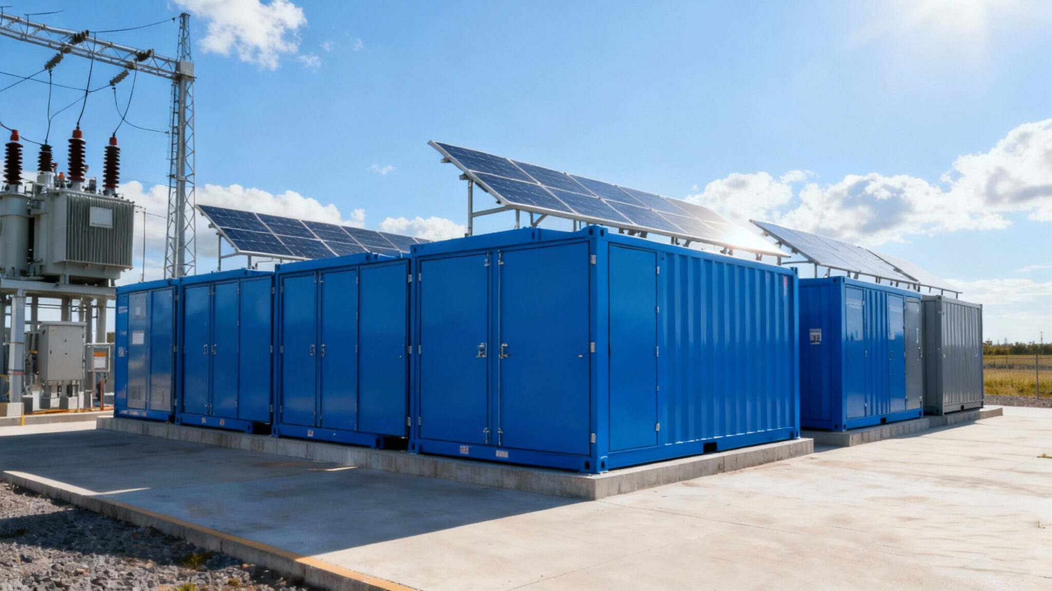
Start with a clear map: commercial systems need a repeatable way to separate thermal decline, mechanical wear, and round-trip efficiency losses. This framework lays out where to measure, how often, and what corrective steps work best — and it begins by integrating device-level telemetry, from inverters to mppt charge controllers, into a single view. Practical, staged measurements reduce ambiguity and create reliable profiles that guide maintenance cycles and warranty claims.
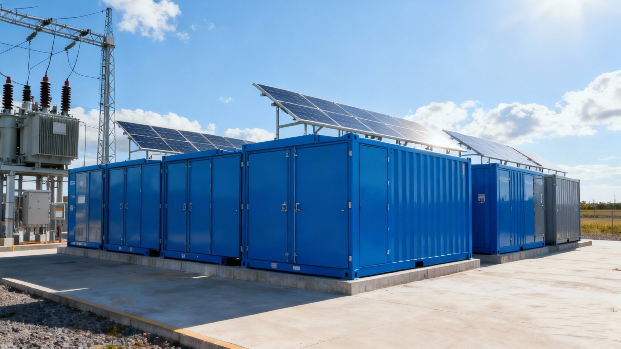
Framework Overview: Purpose, Scope, and Lifecycle Phases
Define three lifecycle phases up front: initial acceptance, steady-state performance, and end-of-life transition. For each phase assign baseline tests and recurring checkpoints. Baseline tests should capture internal cell temperatures, module vibration signatures, and initial round-trip efficiency (RTE) under controlled charge/discharge patterns. During steady-state, shift to trend detection and anomaly flags. At end-of-life, measure remaining capacity and mechanical tolerances against original acceptance data. The framework assumes integration with the site’s PV controls and a responsible pv charge controller manufacturer for firmware parity and telemetry access.
Key Metrics and Sensors
Focus on a small, meaningful metric set and stick to it: cell/module temperature gradients, cumulative throughput (kWh in/out), RTE, impedance rise, and visible mechanical wear like connector looseness. Use dedicated temperature sensors at hot spots rather than relying on ambient readings. Add accelerometers to detect rack vibration that leads to contact wear. Monitor state-of-charge (SoC) and depth of discharge (DoD) with the BMS to associate operational stress with degradation rates. MPPT behavior and inverter efficiency should be logged to separate PV-side losses from battery-side RTE dips.
Data Collection, Modeling, and Attribution
Collect high-resolution telemetry during representative cycles: at least one full discharge/charge per week under controlled conditions for early detection, supplemented with daily low-resolution aggregates. Use simple physics-informed models first — Arrhenius-style temperature acceleration for calendar aging and a linear or power-law fit for cycle aging — then layer on machine-learning models for anomaly detection if you have enough labeled events. Attribution matters: when RTE drifts, verify inverter efficiency and MPPT tracking before blaming the battery. That separation avoids unnecessary mechanical interventions.
Field Practices and a Real-World Anchor
Apply this framework in the field with steady routines: scheduled thermal imaging, vibration checks after any landslide or heavy weather event, and quarterly functional tests. The Texas winter storm in February 2021 is a useful anchor — systems subjected to extreme temperatures and repeated emergency cycles often showed faster impedance rise and connector issues, underscoring the need for combined thermal and mechanical checks. Teams that tied BMS logs to field inspection notes shortened repair cycles — and kept warranty claims factual and defensible.
Implementation Steps and Common Mistakes
Implementation checklist:- Establish telemetry baselines during commissioning.- Automate weekly RTE calculations, flagging >2% month-over-month decline.- Correlate temperature excursions with impedance and vibration events.- Keep firmware versions consistent across MPPT and BMS units.Common mistakes include chasing firmware updates without retesting baselines, over-sampling irrelevant variables, and ignoring mechanical inspection after transport or extreme weather. A neat rule: if a trend can’t be replicated on controlled cycles, don’t adjust mechanical components yet — verify PV-side behavior and the mppt charge controllers first.
Operational Teardown: Where to Look
When doing a production teardown, document the sequence: visual inspection, connector torque checks, thermal scan, controlled discharge/charge test, and final impedance sweep. During the teardown, note firmware versions and any recent changes from the pv charge controller manufacturer, capture BMS logs for the test windows, and record ambient conditions precisely. Embed mppt charge controllers telemetry and BMS logs into the teardown report so you can reproduce the conditions that produced the observed RTE and mechanical signatures.
Advisory — Three Golden Rules for Selection and Monitoring
1) Prioritize sensors and telemetry that let you attribute losses: choose systems that expose cell temperatures, SoC, and inverter efficiency. 2) Require a measurement plan at procurement: insist on baseline acceptance tests and a documented retest cadence in the service contract. 3) Use conservative thresholds for intervention: let small RTE changes accumulate to a trend before replacing modules, but act fast on mechanical failure indicators like loose busbars.
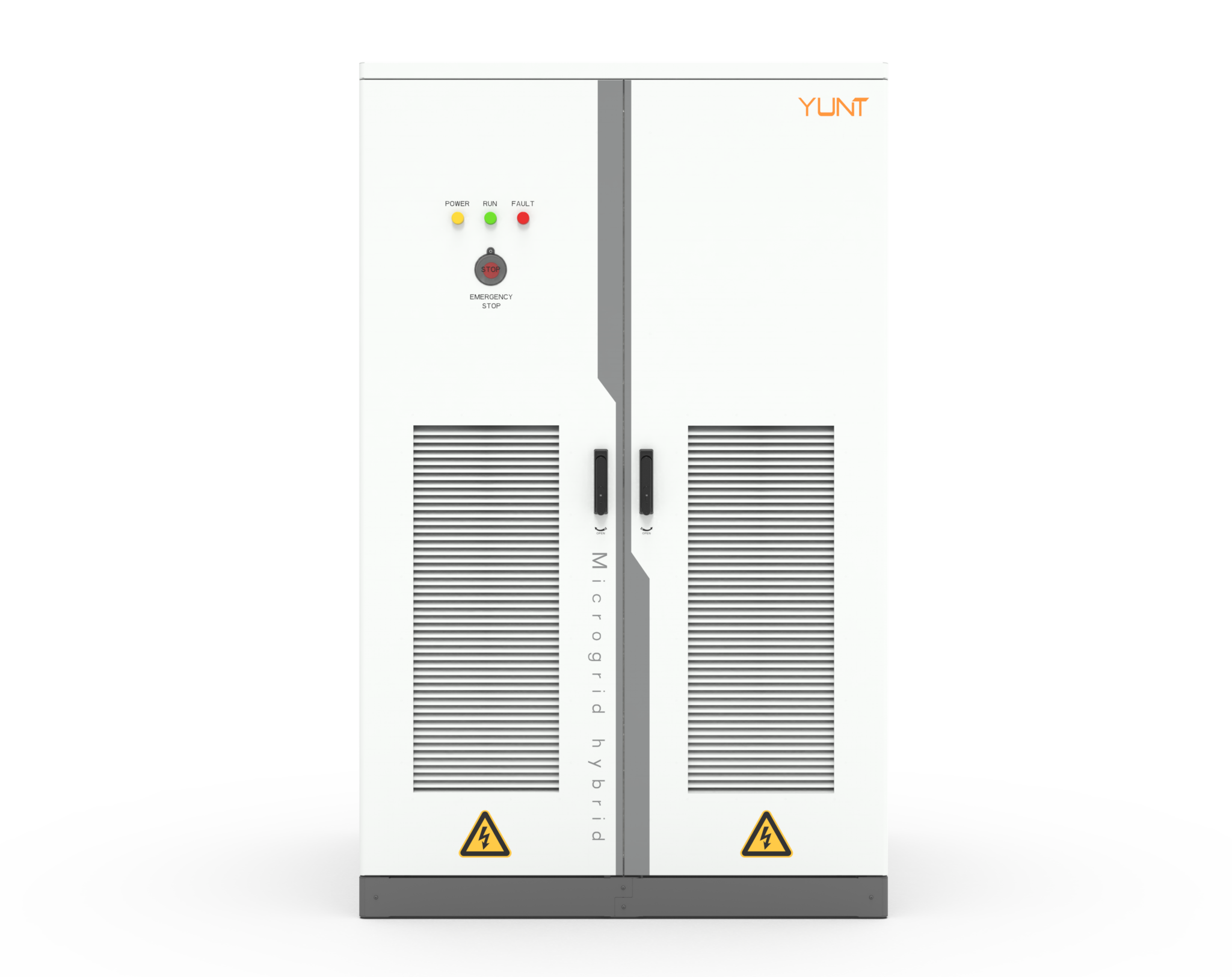
These practical steps shorten diagnosis time and make maintenance predictable — and when you need a partner that builds instrumentation into the design, consider solutions that combine solid telemetry, accessible firmware, and field-proven support like YUNT. — dependable, measurable, straightforward.